How to Test a PCB: Manual Bench Testing vs an Automated Cobot Test Cell
Start With the Board’s Requirements, Not the Test Equipment
Learning how to test a pcb starts with defining what a working board should do. A continuity beep cannot prove that firmware boots correctly, and a successful boot does not confirm that every interface works.
Manual bench testing suits prototypes, unfamiliar faults, and changing designs. An automated cobot test cell suits repeatable handling and established test sequences. Both need documented limits, reliable electrical connections, and a clear process for reviewing failures.
The practical goal is to choose checks that catch relevant defects without damaging the board or creating misleading results.
Prepare Before Connecting Power
Gather the reference information
Start with the schematic, bill of materials, assembly drawing, board revision, and available firmware notes. Identify supply rails, ground points, connectors, test pads, and components with polarity requirements.
Write down the expected input voltage, startup behaviour, normal operating current range, and essential functions. Use design specifications or component documentation rather than guessing from a similar-looking board. A known-working sample helps with comparisons, but it should not replace acceptance criteria.
Set up a suitable bench
Typical equipment includes:
- A digital multimeter for resistance, continuity, diode checks, and voltage measurements.
- A regulated bench supply with adjustable electrical current limiting.
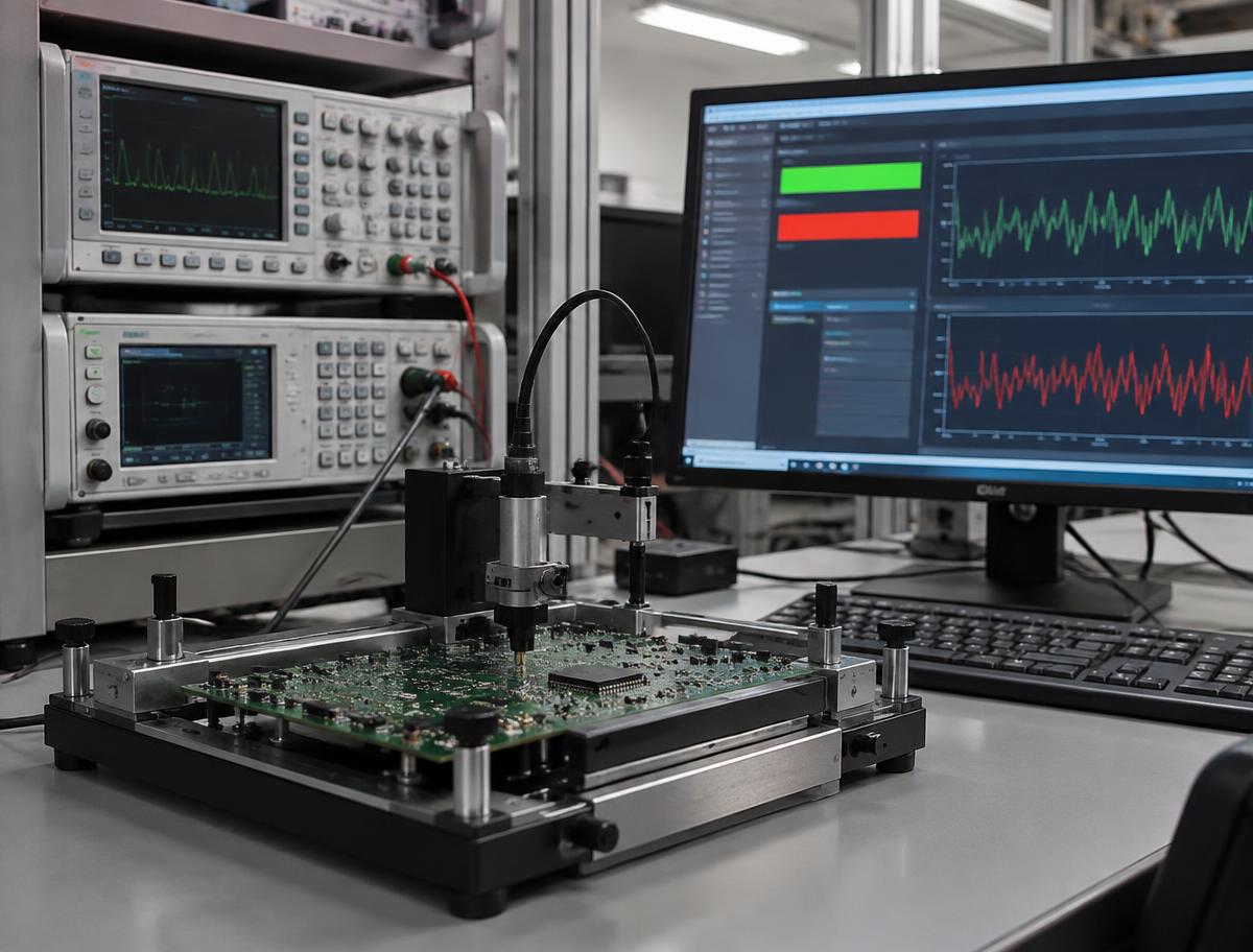
- An oscilloscope with probes suitable for the expected signals and voltages.
- Magnification, good lighting, and appropriate ESD controls.
- A board holder, insulated leads, and documented test connections.
Disconnect power before resistance or continuity measurements. Discharge stored energy using an appropriate procedure and verify that the circuit is de-energised. Never assume an oscilloscope ground clip can connect safely to any node.
Mains-connected circuits, high-voltage assemblies, and large energy-storage components require qualified personnel and equipment selected for those hazards.
How to Test a PCB Manually
1. Inspect the unpowered assembly
Check component orientation, connector alignment, missing parts, visible solder bridges, damaged tracks, and contamination. Compare the assembly with the correct board revision.
Pay particular attention to polarised capacitors, diodes, integrated-circuit orientation, and connectors that could be fitted incorrectly. Visual inspection can reveal obvious defects, but it cannot verify hidden joints or prove electrical performance.
Record suspicious areas before cleaning or rework so the original condition remains traceable.
2. Check for shorts and open connections
Measure resistance between each supply rail and ground before applying power. Unexpectedly low resistance warrants investigation, but it is not automatically a short: some circuits naturally present low resistance, and capacitors can cause changing readings.
Use continuity checks to investigate suspected broken tracks, connector paths, and solder joints. Remember that a meter’s continuity threshold is not a product acceptance limit. Parallel paths can also make in-circuit component readings misleading.
Where necessary, isolate part of the circuit or follow a documented diagnostic procedure.
3. Power up under controlled conditions
Confirm supply polarity and voltage before connection. Set an electrical current limit appropriate to the design and expected startup demand, then observe the first power-up.
Stop if current draw is unexpected, the supply repeatedly enters limiting, or there are signs of overheating or damage. An excessively restrictive limit can also prevent normal startup, so interpret the result against the board’s requirements.
Measure the supply input and regulated rails at specified points. Record actual values and operating conditions, not just a pass label.
4. Check signals and functions
Once the rails behave as expected, check reset, clock activity, communication interfaces, and relevant analogue signals. Select probe methods and bandwidth appropriate to the measurement; probing itself can disturb some circuits.
Then exercise the board’s intended functions using defined inputs and loads. For example, an interface board might need to receive a command, switch an output, and return a status message.
Keep functional testing separate from diagnosis. A failed communication test identifies a symptom, not necessarily its cause.
5. Document and route the result
Log the board identifier, hardware revision, firmware version, test procedure version, measurements, and failure observations. Route failed boards for review rather than repeatedly retesting until one attempt passes.
If retesting is permitted, define when it is allowed and preserve both the original result and subsequent outcome.
What Changes in an Automated Cobot Test Cell?
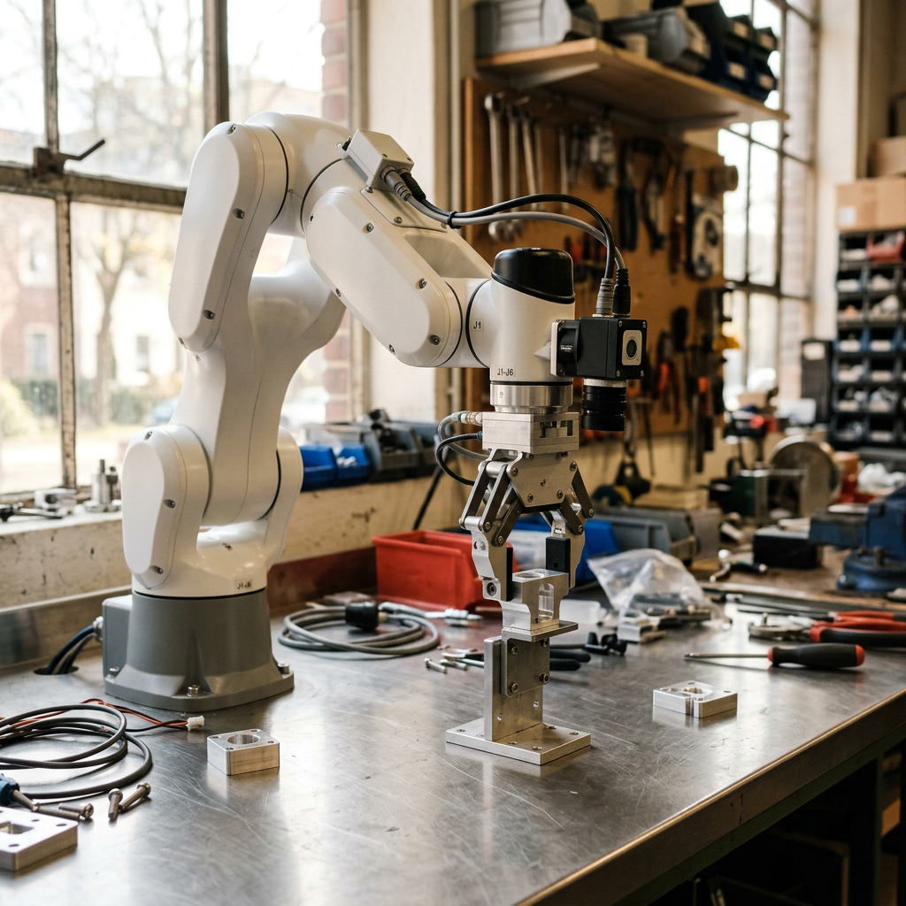
A cobot does not replace the electrical tester. It handles repeatable physical tasks around instruments, fixtures, and test software.
A typical sequence is:
- Present a board in a controlled tray position.
- Use the cobot to transfer it into a locating fixture.
- Confirm placement and fixture closure through suitable interlocks.
- Run the electrical or functional test recipe.
- Save measurements and the recipe version against the board record.
- Unload to a pass location or a review location.
For many boards, a dedicated fixture provides test contact through spring probes or connectors. The cobot handles loading and unloading rather than attempting to place handheld meter probes on individual pads.
Fixtures should account for board tolerances, component clearance, connector wear, and access for maintenance. Boards requiring manual cable attachment may need fixture redesign before automation becomes worthwhile.
Explore the approach on smert.ai’s PCB test and diagnosis page.
Use computer vision as a review aid
Computer vision can detect visible conditions such as board presence, orientation, or apparent component placement discrepancies, then flag them for human review. It does not replace electrical testing or establish the condition of hidden joints.
Lighting, camera position, board finish, and product variations all affect the inspection setup. Evaluate representative samples before setting expectations. See smert.ai’s computer vision services for related integration options.
Manual Bench Testing vs a Cobot Test Cell
| Consideration | Manual bench testing | Automated cobot test cell | |---|---|---| | Best fit | Prototypes and investigation | Stable, repetitive workflows | | Design changes | Easier to accommodate | May require fixture and recipe updates | | Diagnosis | Flexible engineer-led probing | Defined checks with failures routed for review | | Handling | Operator-dependent | Programmed around controlled presentation | | Records | Depend on logging discipline | Can be captured by integrated test software | | Main investment | Instruments and engineering time | Fixtures, integration, instruments, and validation |
Automation is not automatically faster. If a firmware download dominates the cycle, improving that step or testing boards in parallel may matter more than automating loading.
Compare total cycle time, operator involvement, changeover effort, fixture maintenance, and failure-review workload. Measure the existing process before estimating savings.
Validate the Process Before Scaling
Pilot one board family with an agreed test procedure. Include known-working boards and documented fault samples representing relevant failure modes. Confirm that test results remain consistent across repeated fixture loading and normal operating variation.
Separate board failures from test-system problems. Poor fixture contact, worn connectors, incorrect recipes, and communication timeouts should not silently become product defects. Define how operators stop the process, recover interrupted cycles, and reconcile board records.
Safety depends on a per-site risk assessment covering the cobot, tooling, fixtures, electrical hazards, access, and recovery tasks. ISO 10218 and ISO/TS 15066 are standards integrators assess against where applicable, not guarantees of a safe installation.
smert.ai integrates cobot arms from established makers; it does not manufacture the arms. With a lab in Tsim Sha Tsui, Hong Kong, and a US branch in Delaware, smert.ai can discuss integration requirements in the context of your workflow. Browse related cobot applications.
FAQ
Can I test a PCB with only a multimeter?
You can check continuity, resistance, diode behaviour, and DC voltages. Verifying timing, communication, and complete functionality may require an oscilloscope, interface tools, loads, or dedicated test equipment.
Should I apply power before checking for shorts?
No. Inspect the unpowered board and investigate suspicious supply-to-ground readings first. Apply power only after confirming the connection details and establishing suitable electrical limits.
Can a cobot diagnose every PCB fault?
No. A cobot performs configured handling tasks. Instruments and software collect results, while unfamiliar or ambiguous failures need human review and potentially additional bench investigation.
When should I automate PCB testing?
Consider automation when board presentation, test requirements, and production demand are sufficiently stable. Pilot the process first to assess cycle time, fixture reliability, maintenance, and exception handling.
Ready to evaluate your workflow? Contact smert.ai with your board dimensions, test requirements, expected volumes, and current bottlenecks.
Related: Cobot integration
Transform Your Business with SMERT Robotics
Ready to experience the benefits of hospitality automation? Our team is ready to help you get started.